<< Back

Compaq Presario SR1703WM Motherboard w/ AMD CPU


Price: $35.00
Compaq Presario SR1703WM Motherboard w/ CPU
Click for full size image.
Item Description
Motherboard specifications table
Part / FeatureSpecification / Support
Motherboard description
  • Motherboard manufacturer's name: ASUS A8AE-LE
  • HP/Compaq name: AmberineM-GL6E
CPU/Processor
  • Socket: 939
  • Supports the following processors:
    • AMD Athlon 64 X2 4800+
    • Athlon 64 4000+
    • AMD Sempron 3200+
Front-side bus (FSB)
  • 2000MT/s or 1600MT/s, depending on what the processor supports
Chipset
  • Northbridge: RS482
  • Southbridge: SB400
BIOS features
  • 4Mb LPC EEPROM
  • HP BIOS with enhanced ACPI, DMI, Green, and PnP Features Plus
Form factor
  • ATX form factor, 9.6 in x 9.6 in
Memory
  • Dual-channel memory architecture
  • 4 x 184-pin DDR DIMM sockets support unbuffered non-ECC 4 GB 400/300 MHZ DDR memory modules
  • Maximum HP/Compaq approved memory is 4 GB*


NOTE: *Actual available memory may be less
Expansion slots
  • Three PCI
  • One PCI Express (No AGP slot)
Video graphics
  • Integrated
Serial ATA
  • 2 SATA connectors
  • Each connector supports 1 serial ATA-150 disk drive
Onboard audio or audio card
  • Controller: AC97 audio
  • Location: Integrated
Onboard LAN
  • Realtek 8101L
  • 10/100 Mbps LAN PHY
Back panel I/O
  • One PS/2 mouse port
  • One PS/2 keyboard port
  • One VGA (monitor)
  • One Parallel
  • Four USB (2.0)
  • One IEEE 1394
  • One RJ-45 networking port
  • One S/PDIF out
  • Audio (line in, line out, microphone)
Internal connectors
  • One 24-pin ATX power connector
  • One 4-pin ATX power connector
  • Two IDE connectors
  • Two SATA connectors
  • One floppy drive connector
  • One CPU fan connector
  • One System fan connector (also known as duct or chassis fan)
  • One system indicator LEDs / power switch / reset button connector
  • One each, front headphone, microphone in, line in (Aux-in)
  • One front panel power and LED connectors
  • Two USB connectors supporting 4 additional USB 2.0 ports
  • One IEEE 1394a connector supporting one 1394a port

NOTE: Motherboard specifications are subject to change without notice.
Motherboard layout and photos
Figure 1: Layout
Figure 2: Photograph
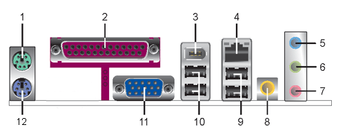
Figure 3: Backplate
1 - PS/2 mouse port (green). This port is for a PS/2 mouse.
2 - Parallel port. This 25-pin port connects a parallel printer, a scanner, or other devices.
3 - IEEE 1394a port. This 6-pin IEEE 1394a port provides high-speed connectivity for audio/video devices, storage peripherals, PCs, or portable devices.
4 - LAN (RJ-45) port. This port allows connection to a Local Area Network (LAN) through a network hub.
5 - Line In port (light blue). This port connects a tape, CD, DVD player or other audio sources.
6 - Line Out port (lime). This port connects a headphone or a speaker. In 4- channel and 6-channel mode, the function of this port becomes Front Speaker Out.
7 - Microphone port (pink). This port connects a microphone.
8 - Coaxial S/PDIF Out port. This port connects an external audio output device via a coaxial S/PDIF cable.
9 - USB 2.0 ports 3 and 4. These two 4-pin Universal Serial Bus (USB) ports are available for connecting USB 2.0 devices.
10 - USB 2.0 ports 1 and 2. These two 4-pin Universal Serial Bus (USB) ports are available for connecting USB 2.0 devices.
11 - VGA Graphic Adapter port. This 15-pin port is for a VGA monitor or other VGA-compatible devices.
12 - PS/2 keyboard port (purple). This port is for a PS/2 keyboard.
Clearing the CMOS settings

CAUTION: Do not change any jumper setting while the computer is on. Damage to the motherboard can result.
Clear RTC RAM (3-pin CLRTC)
This jumper allows you to clear the Real Time Clock (RTC) RAM in CMOS. You can clear the CMOS memory of date, time, and PC setup parameters by erasing the CMOS RTC RAM data. The RAM data in CMOS, that include PC setup information, is powered by the onboard button cell battery.
  1. Turn OFF the PC and unplug the power cord. This motherboard has a jumper to clear the BIOS settings in CMOS RAM.
  2. To clear BIOS settings, temporarily set the jumper labeled "CLEAR CMOS" to pins 1-2.
  3. Wait at least 6 seconds and then return the cap to pins 2-3. When you start the PC you will need to enter BIOS setup to reset any custom BIOS settings.

CAUTION: Except when clearing the RTC RAM, never remove the jumper from the default position. Removing the jumper causes PC startup failure!
1 - Clear CMOS
2 - Normal (default)

Clearing the BIOS password

The BIOS password protects the BIOS from undesired changes. If password checking is enabled, and you need to disable it, use the following steps:

CAUTION: Do not change any jumper setting while the computer is on. Damage to the motherboard can result.
  1. Turn OFF the PC and unplug the power cord.
  2. Move the jumper labeled "CLEAR P.W" to pins 1-2.
  3. Wait at least 6 seconds and then return the jumper to pins 2-3.
  4. Plug the power cord and turn ON the computer.
  5. Hold down the F1 key during the startup process and enter BIOS setup to change or clear the password.

CAUTION: Except when clearing the RTC RAM, never remove the jumper from the default position. Removing the jumper causes PC startup failure!
 
Payment Details


Credit or debit card through PayPal
Accepted

Immediate payment required for this item

Shipping Details

We offer free shipping on all PC parts.

Our Refund Policy

100% money back with all orders with in 7 days.

-     Feedback   -   About Me   -   Other Auctions   -
eBay HTML templates
eBay HTML templates at BiggerBids.com.
Return
Items must be returned within 7 days .
Refund will be given as Money back.
Refund policy details:
null
Shipping

Destination: United States

CarrierMethodShipping CostPer additional Item
STANDARDStandard$0.00
Payment Method

Type

Instructions to Buyer

Paypalnull
Insurance
Not Offered (Domestic)
 

Shopping Cart


-Your cart is empty.-

Online Store Powered by Vendio | Privacy Policy